24/May/99: Started as a new file in its own right.
| 07/June/99: Figured out the meaning of the first big T-10, the little
T-10's and most of the second big T-10; a few rewrites. 24/May/99: Started as a new file in its own right. |
A note about numbers. TRK numbers are large integers (i.e. 20100000). These numbers are actually 1/500ths of an inch, so to turn them into metres (as used by the 3DO's), divide by 19685.03937, or more accurately, 31680/1.609344. The track 3do's use TRK numbers in several places, probably to confuse anyone looking at the files...
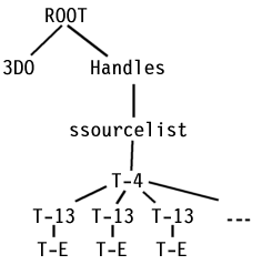
This diagram shows the layout of kyalami.3do:
This is where the tracks get interesting, hehe...
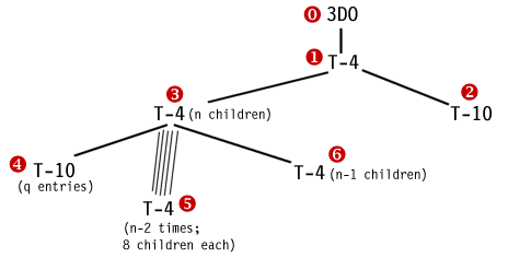
![]() is a T-4 node with two children.
is a T-4 node with two children.
The second of these, ![]() , is a list of numbers. The number of these is always a multiple of
4 (for all the standard GPL tracks, anyway), and is equal to the track length
in metres divided by 39.0m (roughly). Kyalami for instance is 3970.49m
in length and has 404 entries in the list. 3970.49 / 101 (101 groups
of 4 = 404) = 39.3m. Thus there is one group of 4 numbers every 39.0m
around the track (39.3 in Kyalami's case, but that is probably due to 3970.49
not being a multiple of 39).
, is a list of numbers. The number of these is always a multiple of
4 (for all the standard GPL tracks, anyway), and is equal to the track length
in metres divided by 39.0m (roughly). Kyalami for instance is 3970.49m
in length and has 404 entries in the list. 3970.49 / 101 (101 groups
of 4 = 404) = 39.3m. Thus there is one group of 4 numbers every 39.0m
around the track (39.3 in Kyalami's case, but that is probably due to 3970.49
not being a multiple of 39).
These groups of 4 are as follows:
The first number appears to be a distance (trk) that things can be seen when
looking forwards.
The third number appears to be the same, but when looking backwards.
The second and fourth are nearly always zero, except at locations like hairpins,
where two pieces of track can be seen at once. I believe that the second
must be the distance forwards down the other piece of track (so that would
be like looking backwards down that piece of track), and therefore the fourth
number must be backwards (forwards) down the other piece of track.
I'm not convinced about these numbers yet... It would appear that GPL
accepts the 4-tuple as 10000000,0,10000000,0 without much complaints (haven't
tried this as hairpins...)
![]() is a T-4 with n children. Of these, the first is
is a T-4 with n children. Of these, the first is ![]() , the next n-2 are
, the next n-2 are ![]() , and the last is
, and the last is ![]() .
.
![]() is a T-10 node with q entries (the letters n and q are entirely not significant).
The value of q is obtained by dividing the track length by 13.3. This
is because there one number for every 13.3 metres (roughly) around the track.
The values of the entries are from 0 to n-3, i.e. there are entries for every
entry in the
is a T-10 node with q entries (the letters n and q are entirely not significant).
The value of q is obtained by dividing the track length by 13.3. This
is because there one number for every 13.3 metres (roughly) around the track.
The values of the entries are from 0 to n-3, i.e. there are entries for every
entry in the ![]() structure. The example track, Kyalami, has 299 entries in this part
of the tree, and they go like this: 0, 0, 0, 0, 0, 0, 0, 0, 0, 0, 0, 0, 0,
0, 0, 0, 1, 2, 2, 2, 2, 3, ..., 88, 88, 89, 89, 89, 89, 89. Kyalami
has n as 92. Thus for Kyalami, if the car is in the first 13.3 metres
of the track, the first 3do section will be used, all the way up to 16*13.3m,
then the second 3do section, then the third for 4*13.3m, etc. Sometimes
the 3do sections will not be listed in this list, because they are too short.
This leads me to believe that GPL uses the 3do sections surrounding the one
the car is in, as well as the one the car is in.
structure. The example track, Kyalami, has 299 entries in this part
of the tree, and they go like this: 0, 0, 0, 0, 0, 0, 0, 0, 0, 0, 0, 0, 0,
0, 0, 0, 1, 2, 2, 2, 2, 3, ..., 88, 88, 89, 89, 89, 89, 89. Kyalami
has n as 92. Thus for Kyalami, if the car is in the first 13.3 metres
of the track, the first 3do section will be used, all the way up to 16*13.3m,
then the second 3do section, then the third for 4*13.3m, etc. Sometimes
the 3do sections will not be listed in this list, because they are too short.
This leads me to believe that GPL uses the 3do sections surrounding the one
the car is in, as well as the one the car is in.
![]() is another T-4, with n-1 children. These children are all T-F nodes.
As will be explained later, these are decidedly nasty...
is another T-4, with n-1 children. These children are all T-F nodes.
As will be explained later, these are decidedly nasty...
![]() is a set of n-2 T-4 nodes. Each of these nodes have 8 children:
is a set of n-2 T-4 nodes. Each of these nodes have 8 children:
| Child no. | Child Node types | What is it? |
| 1 | T-B, T-8 or NULL | highest level of detail |
| 2 | ||
| 3 | ||
| 4 | ||
| 5 | T-B, T-8 or NULL | middle level of detail |
| 6 | ||
| 7 | T-B or T-8 | far away level of detail |
| 8 | T-10 | a list of 4 TRK numbers |
These nodes define 3 levels of detail of track graphics. When viewed from far-away, this section of track (i.e. Kyalami has 90 visible track sections) is represented by one region, as defined in the sub-tree 7. When viewed from closer to, the section is broken into two regions, 5 and 6. Closer still and the section consists of 4 regions, 1-4.
It is not necessary to define region 6 - it can be a null entry (5 is always required). If 6 isn't defined, regions 3 and 4 will never be defined. If 6 is defined, region 4 may be non-existent. Similarly, region 2 may be non-existent. If regions are not defined, the regions that are defined must cover the regions that are not.
To get it out of the way, the last entry, 8, is a T-10 node with 4 entries.
These entries are TRK lengths, i.e. divide by 19685.xxx to turn them into
metres. They give the starting position around the TRK line of each
region. For straights, all 4 numbers will (nearly always) be the same.
Corners usually have 4 different numbers, the first for the first region,
second for second, etc.
Regions, for want of a better description:
These contain all the graphical details that we're already familiar with - polygons, as well as some T-F nodes, T-19's and some other bits and pieces.
Think of a region as being a segment of track, from the far left wall to the far right wall, of say distance 12 metres (just an example distance, each region is usually a different length). The 7th region will thus cover all of this area. The 5th and 6th will cover 6 metres each, and the 1st-4th will cover 3 metres each.
The node that starts off the section is one of two types (ignoring the null entries now), T-B or T-8. The difference between the two is that T-B is used where there is not a wall, fence, etc., and T-8 is used when there is. T-8's - not used elsewhere very often - are used to split the region into four - the two bits of land either side of the wall, and the two sides of the wall. There are two T-8's/B's and lots of other bits, best explained with another diagram:
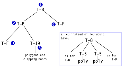
I do not know which of ![]() and
and ![]() is left and which is right. I believe the first is the left, but it
probably all depends on how the planes and sub-structure is all oriented.
The same goes for the two polygons in the T-8's - one is left and one is
right...
is left and which is right. I believe the first is the left, but it
probably all depends on how the planes and sub-structure is all oriented.
The same goes for the two polygons in the T-8's - one is left and one is
right...
Anyway, on with the structure.
![]() &
& ![]() : Outside the walls (or lack of walls - think of them always being there,
just invisible. They are not the edge of existence, just the edge of
the track) is the region in which the trackside objects exist - all referenced
via the two T-F structures.
: Outside the walls (or lack of walls - think of them always being there,
just invisible. They are not the edge of existence, just the edge of
the track) is the region in which the trackside objects exist - all referenced
via the two T-F structures.
![]() : In between the 'walls' is the visible part of the track - all defined under
the T-19 node, which is a volume defining node. I believe this is to
define the region in which cars are supposed to be. It is 3D and covers
the entire region between the two walls and start and end of the region.
The sub bits of
: In between the 'walls' is the visible part of the track - all defined under
the T-19 node, which is a volume defining node. I believe this is to
define the region in which cars are supposed to be. It is 3D and covers
the entire region between the two walls and start and end of the region.
The sub bits of ![]() are all the sort of 3DO structure that is used everywhere, apart from the
fact that the T-F nodes rear their ugly heads again. This allows for
sub-3DO's to be placed within the walls. I believe there is one sub-region
in this part of the structure per bit of the T-F structure.
are all the sort of 3DO structure that is used everywhere, apart from the
fact that the T-F nodes rear their ugly heads again. This allows for
sub-3DO's to be placed within the walls. I believe there is one sub-region
in this part of the structure per bit of the T-F structure.
And now for something completely scary...
T-F's!
Unfortunately I cannot get away without explaining these, as they are so
well integrated with the rest of the structure that to leave them out would
be stupid. Grrr... T-F's tell GPL where external 3DO objects
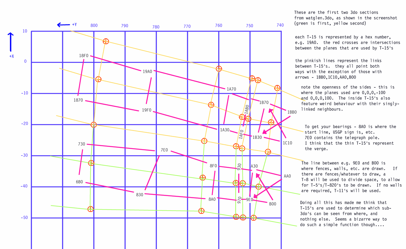
are located. They work as a grid covering the entire visible area,
and even extending off to infinity track-left and track-right. Thus
3DO's can be placed anywhere by adding them to the appropriate T-F node (or
nodes - a grandstand might be in more than one T-F...)
OK then, This huge diagram shows the T-F areas from Watkins Glen (the first few, covering the starting line onwards). As you can see, I drew this back in Februrary, but the comments down the side are still relevant.
What I haven't said is that each area is defined by 4 planes. The
space within each of these is the area defined. (?)
The actual polygons and so on fit into the confines of the areas, but there
may be more than one polygon per area - e.g. a bit of track, kerb and a bit
of semi-transparent racing line.
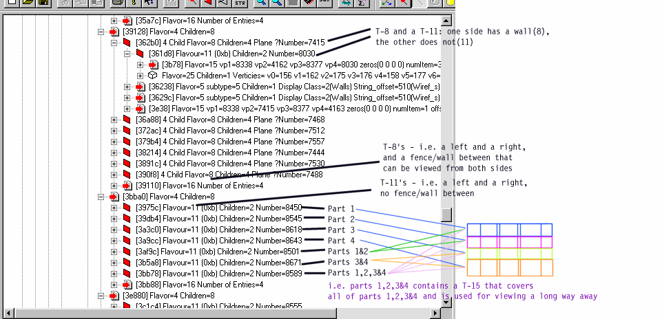
Lastly, for now, this diagram shows pretty much all of what I've been explaining, in GPLEditor by Paul Hoad. Please note that Paul uses decimal notation (not that that's bad in any way) for the node types (called flavours below), so T-8 = flavour 8, T-B = flavour 11, etc.
