Header; Normals; Vertices; Planes; Strings; Primitive Tree(s); Handles
This page will hopefully explain the way in which these work together to create the objects used in GPL. Hopefully. If you are new to 3DOs, I recommend you take your time and read all of the pages here several times over before doing anything. Unless you think it's all too easy ;-)
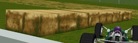
I'll assume an understanding of 3D vertices and the fact that polygons can be constructed from those vertices. In the hay bale (bale?, bail?), only rectangles are used.

Take a wall that has two sides (forget the thickness for now). When you are standing on one side, unless you have some really cool vision, you can't see the other side (also forget mirrors and such). If you move around to the other side, you can't see the side you were on. Thus, to reduce the number of polygons drawn by half, all that is needed is a way to determine which side of the wall you are on. The same goes for objects which are on opposite sides of a surface. If you have an apple behind a wall, it is fairly safe to say that it won't be visible from in front of the wall (unless the wall has lots of holes, in which case it is pointless to use visibility determination like Hidden Surface Removal - a depth buffer is much more useful - but forget this little side point if you're confused already).
To determine which side of a plane (an infinitely thin surface, extending to infinity in all other directions), a point (i.e. an observer) is on, maths is used. The equation of the plane (Ax + By + Cz + D = 0) is jiggled about a bit with the location of the viewer and a number results. If negative, the viewer is one side, positive the other, zero and the viewer is actually on the plane (and thus in a bizarre infinity reality Star Trek situation and can't see anything (or can they?)).
Back to the hay bale, and you'll see 5 numbers from 0 to 4. These reference the red squares/lines, which are the planes for the hay bale. Most planes you'll encounter will be in the same plane as a polygon, like those in the example. It is not necessary for this to be the case, but it usually helps. The numbers are the same as used by GPL.
Now we need to see the 3DO as a tree:
When GPL comes to render the hay bale (or any other object), it starts
at the top of the tree (T-9,2) and sees which side of plane number 2 the viewer
is on. Looking at the diagram, it can be seen that if the viewer is
above the plane (in the direction of the line), they can see the contents
of the left hand branch (which is actually the middle branch, because no
left branches are defined for this particular object). Presumably,
if they are below the plane they would be shown the contents of the left
hand branch. The rendering then continues by following the right hand
branch, where similar checks are made.
The T-6 node is a bit different in that it does not contain anything other
than a single branch which is followed if the viewer is in front of the plane,
otherwise is isn't.
Remember that planes are infinite, and divide space into two. If you take several planes, it is possible to define a region of space which is behind all of the planes, i.e. enclosed. GPL uses this (not enclosed top and bottom, though), to define volumes where collisions occur. This is achieved by using a tree of a particular structure:
This tree is contained within the hay bale's 3DO as a separate tree. A Handle is used to point to the tree, under the name 'collision'. (see the Handles section for more information). The number of children in the first T-4 defines how many volumes make up the collision detection, for there can be more than one. For each volume, a T-4 has n children, one per plane, that consist of a T-6 (with the appropriate plane id), and a T-10, which lists numbers. For collision volumes, there is only ever 1 number, for this example it is 0xB, or 11decimal, which presumably means hay, or more accurately, a solid collision. I haven't yet researched the different types of collision available. Needless to say there are types with different rebound characteristics, and types like hedges, that 'catch' the car.